Logic Tree
About Logic Tree
In a Root Cause Analysis, analyzing data involves compiling the information that has been collected so far in the Root Cause Analysis and representing it visually to facilitate discussion. A Logic Tree is an organizational tool that you can use to diagram all the possible causes of a failure event.
Details
The Logic Tree lets you represent visually the events that are associated with a failure and the cause-and-effect relationships that may have led to a failure event. The structure of the Logic Tree is hierarchical so that you can easily reference which event caused what effect. Each cause or effect is represented by a labeled icon, called a node. You can add nodes to the Failure Event node that represent components of the Root Cause Analysis. For example, if you define the Failure Event node as a fire, in the Logic Tree, you would add to the Failure Event node downstream nodes that represent all the possible causes for the failure event.
The following list provides the types of nodes that you can use in a Logic Tree Diagram:
| Icon | Node |
|---|---|

| Failure Event |

| Failure Mode |

| Hypothesis |
 or or 
| Logic Gate |
Each node has an associated, which participates in a predecessor-successor relationship. For example, each Failure Mode node that appears in the Logic Tree has an associated RCA Failure Mode that is linked to the root RCA Event. Additionally, for each Hypothesis node that appears in the Logic Tree, an associated RCA Hypothesis exists that is linked to the predecessor RCA Failure Mode and the root RCA Event. Additionally, when you add a node to the Logic Tree, a link is created between that node and the RCA.
The following image illustrates the basic structure of the Logic Tree. For more information on each level of the Logic Tree, select the link that contains the name on the associated node in the image.
Difference Between an Event Diagram and a Logic Tree
The Event Diagram can depict the cause-and-effect of events that led to the failure event and post-failure activities. The Logic Tree, however, can depict, starting with the failure event, possible causes and hypotheses related to the event itself.
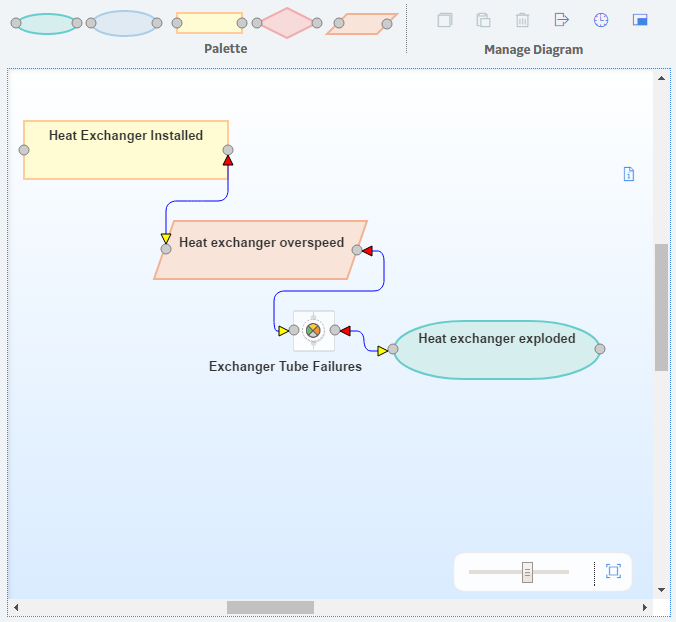
The Event Diagram enables the RCA Team to view and organize the chain of events prior to the failure event and identify possible work process issues. The following image shows an Event Diagram that was created in the Event Diagram workspace.
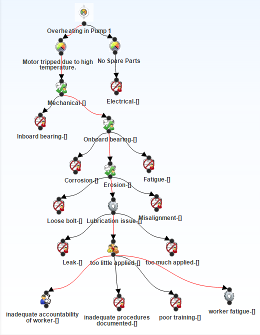
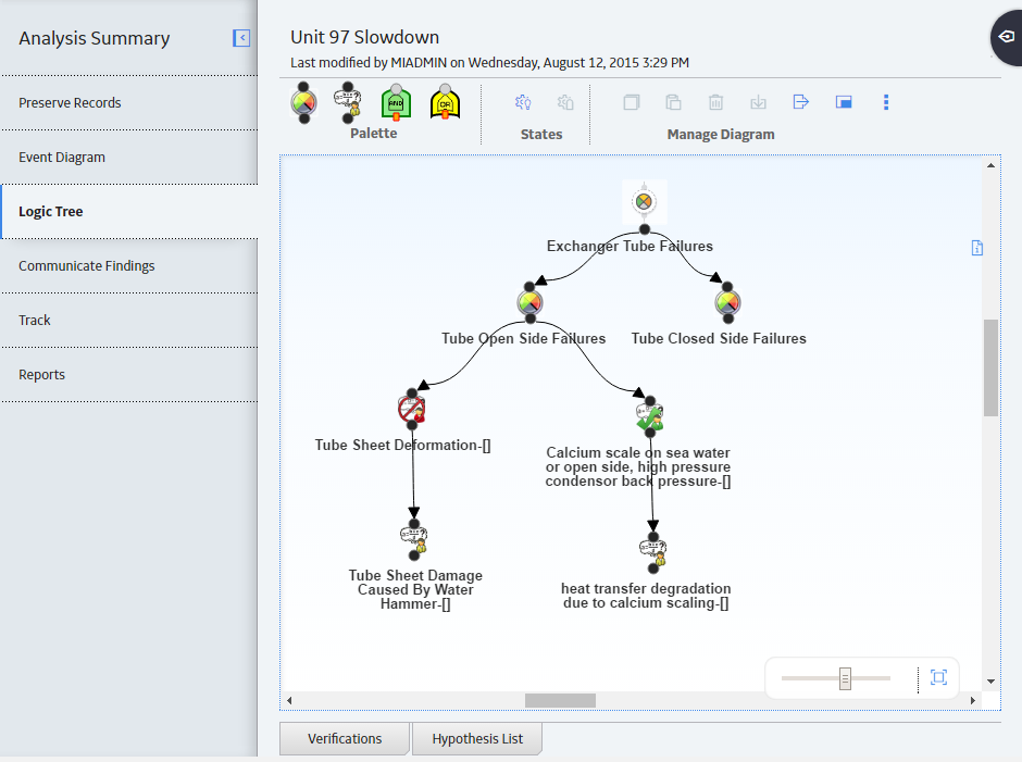
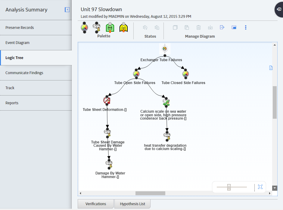
The Logic Tree can depict, starting with the failure event, possible causes and hypotheses related to the event itself. The Logic Tree enables the RCA Team to organize and discussion points on the possible causes of the failure event. The following image shows a Logic Tree that was created using options in the Logic Tree workspace.
Event Diagram and Logic Tree Data Model
An Event Diagram and a Logic Tree consist of an RCA Event and all the records that are linked to it directly or indirectly. For example, after you define the failure event, you can create RCA Failure Modes to link to the RCA Event, and then you can link RCA Hypothesis to the RCA Failure Modes, and so on.
The following image shows the entity families and relationship families that are used to create an Event Diagram and a Logic Tree in Root Cause Analysis. The Logic Tree and the Event Diagram share an RCA Event. The RCA Sequence Node family is used only by the Event Diagram. All of the other families are used by the Logic Tree.
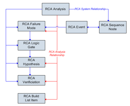
Records in the RCA Logic Gate family can be linked to others in the RCA Logic Gate family. Additionally, records in the RCA Sequence Node family can be linked to others in the RCA Sequence Node family.
In addition to the relationships that appear in the images, the following families can be linked to records in the RCA Reference Document family through a relationship definition on the Has Reference Documents family:
- RCA Event
- RCA Hypothesis
- RCA Logic Gate
About Failure Events
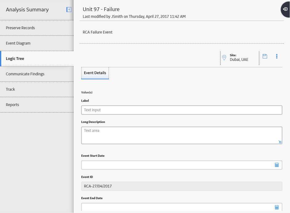
The failure event is a short description of the problem that you and your team are analyzing. Your team could be analyzing a failure event that comprises several failures over a specified period of time, or one failure (e.g., a larger event, such as a fire). The first time that you access the Event Diagram workspace or the Logic Tree workspace for a given RCA, you will be prompted to define the failure event in an RCA Event, which will be used as the Failure Event node. The following image shows an example of a completed RCA Event.
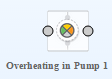
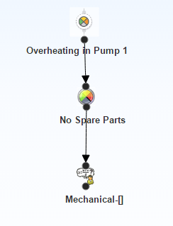
Each RCA will have one Failure Event node, which will always appear at the root level of the Logic Tree hierarchy and as the first node in the Event Diagram. For example, the following image shows the Failure Event node as it appears in the Logic Tree in our Cooling Water Pump example.
You cannot remove the Failure Event node from the Logic Tree or the Event Diagram. You can, however, modify the RCA Event, as needed.
About Failure Modes
A failure mode is a possible cause associated with the failure event. The failure mode is represented by a node, called the Failure Mode node, which appears below the Failure Event node. When you add a Failure Mode node to the Logic Tree, you are defining the RCA Failure Mode. When you define an RCA Failure Mode, a link is created between the RCA Failure Mode and the root RCA Event and between the RCA Failure Mode and the RCA.
Failure Mode nodes exist on the second level of the tree, under the Failure Event node. Multiple Failure Mode nodes can be linked to the Failure Event node. The following image shows an example of how a Failure Mode node will look in the Logic Tree.

A given failure event can have multiple failure modes. For example, the image shows the failure modes from our Cooling Water Pump failure example. The Failure Event node (i.e., the overheated pump) is associated with the following Failure Mode nodes:
- No Spare Parts: There were no spare parts when the pump overheated, which caused the pump to be down for a longer amount of time and a greater loss of production. This failure mode did not cause the failure, so there are no hypotheses associated with it, but it is included as part of the failure event.
- Motor tripped due to high temperature: This failure was the cause of the overheated pump event. There are additional hypotheses associated with this node so that the cause of the event can be determined.
About Hypotheses
By definition, a hypothesis is a tentative assumption intended to explain certain facts or observations. For a Root Cause Analysis, a hypothesis represents a theory about the root cause of a failure event. RCA Hypotheses are then assigned a state that indicates the validity of the hypothesis.
Details
In the Logic Tree, a hypothesis is represented by a Hypothesis node, which is defined in an associated RCA Hypothesis. Hypothesis nodes can appear below Failure Mode nodes and other Hypothesis nodes in the Logic Tree. When you add a Hypothesis node to the Logic Tree, a link is created between the RCA Hypothesis and the RCA. A link is also created between the RCA Hypothesis and either the RCA Failure Mode or the predecessor RCA Hypothesis.
The following image shows an example of how a Hypothesis node and the associated RCA Hypothesis will look in the Logic Tree when it is first created.
To the right of the label that you assign to the Hypothesis node, a number appears, indicating the level of confidence that the team has in the hypothesis being true. After a given RCA Hypothesis has been created, the team can create an RCA Verification to test the hypothesis. The team will then change the state of the RCA Hypothesis according to the results of the RCA Verification.
You can define multiple Hypothesis nodes for any RCA Failure Mode or RCA Hypothesis, meaning that one cause could have been caused by something else. For example, a lubrication issue may cause a cooling water pump to overheat, but that lubrication issue was caused by an operator who did not apply enough lubricant, which was caused by inadequate accountability of workers. In this case, the lubrication issue is a physical cause, too little lubrication applied is a human cause, and the latent root cause is the inadequate accountability of workers. The following image shows how this scenario would appear in the Logic Tree.
About Hypothesis States
After the hypothesis has been tested through the completion of an RCA Verification, the state of the Hypothesis node can then be changed to True or Not True. If a hypothesis is proven to be incorrect, after you change the Hypothesis state to Not True, you are finished working with that hypothesis. If a hypothesis is proven to be true and you change the Hypothesis state to True, you can:
- Create additional RCA Hypothesis records that provide further information on a root cause and link them to the RCA Hypothesis.
-
Create RCA Verifications to test the additional hypotheses, determine if the hypotheses are true or not true, and then change the state of the associated RCA Hypothesis records accordingly.
- Create additional RCA Verifications to test the hypothesis to further identify the root cause as physical, human, or latent.
After the root cause has been identified, you can change the state of the associated RCA Hypothesis to indicate your conclusions (i.e., Cause Human, Cause Latent, or Cause Physical).
When you change the state of a Hypothesis node, the node icon changes to indicate the new state. The following table describes all the possible states of an RCA Hypothesis and how the associated Hypothesis node will appear in the Logic Tree.
| Hypothesis Node | Hypothesis State | Description | For example, the team may determine that: |
|---|---|---|---|

| Hypothesis | The hypothesis is proposed and no conclusions can be drawn at this point. This is the default state. | The piece of equipment may have failed due to a pressure leak. |

| Hypothesis True | The hypothesis has been tested and proven to be correct. Further conclusions can be drawn. | The piece of equipment failed due to a pressure leak. |

| Hypothesis Not True | The hypothesis has been tested and proven to be incorrect. No further conclusions can be drawn. | The piece of equipment did not fail due to a pressure leak. |

| Cause Human | The hypothesis has been proven correct and further testing has revealed that the root cause of the Failure Event was caused by human interaction. | The operator failed to increase the pressure when it reached the critical level, therefore causing a pressure leak and the failure. |

| Cause Latent | The hypothesis has been proven correct and further testing has revealed that the root cause of the Failure Event was caused by flaw(s) in procedure or the system that caused incorrect decisions to be made. This is often due to poor data or communication between individuals within the organization. In the vast majority of events, there will be at least one latent cause. | Management failed to adhere to the recommended safety guidelines for the piece of equipment, thus the operator failed to increase the pressure when it reached the critical level, causing the pressure leak and the failure. |

| Cause Physical | The hypothesis has been proven correct, and further testing has revealed that the root cause of the Failure Event was caused by a physical piece of equipment. | The seals on the pressure relief valve are worn and require replacement, which caused the pressure leak and the failure. |
About Verification
A verification is a task to prove or disprove a hypothesis. An RCA Verification contains the task-related information required to verify a hypothesis. The RCA Verifications are assigned to team members, similar to the way in which RCA Preserve Records are assigned. For example, if you wanted to verify whether a pump overheated because of a mechanical or electrical problem, you would need to inspect the pump's wiring.
About Logic Gates
You can add logic gates to the Logic Tree to define a connection between nodes. A logic gate is defined in an RCA Logic Gate and is represented in the Logic Tree by a Logic Gate node. You can use Logic Gate nodes to add Boolean logic between nodes (i.e., AND and OR statements). The AND Logic Gate is represented by the  symbol in the Logic Tree. The OR Logic Gate is represented by the
  symbol in the Logic Tree.
Details
Adding a Logic Gate node between other nodes in the Logic Tree indicates a conditional relationship between the nodes, which you can define in the description fields in the RCA Logic Gate. These conditional relationships are defined in logical statements (e.g., if B is true, then A is true).
When two or more hypotheses are linked to a common predecessor node, the hypotheses nodes are by default connected using the OR Logic Gates, whether the Logic Gates are visible or not.
To add a Logic Gate node manually to the Logic Tree, you will need to enable logic gates and create an RCA Logic Gate.
Example: Logic Gates
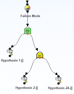
Assume that you want to indicate in the Logic Tree that Failure Mode is true only if Hypothesis_1 and Hypothesis_2 or Hypothesis_2A is true.
You would organize the nodes in the Logic Tree as shown in the following image.
Access the Logic Tree Diagram
Procedure
- In the left pane, select the Logic Tree tab.
The Logic Tree diagram for the selected RCA appears in the workspace.
 Tip: Select
 to display the diagram in full screen.Note: If you access the Logic Tree tab for the first time, the RCA Failure Event window will appear, where you can define an RCA Failure Event. If you previously accessed the Logic Tree tab and defined a Failure Event, you will see the Failure Event node in the main display area (i.e., the design canvas).
Create a Failure Event
About this task
When you create an RCA Event, you are also defining the associated Failure Event node. After you create a Failure Event node, you cannot delete it via Root Cause Analysis, but you can modify the RCA Event. Only one RCA Event can be defined for each RCA.
This topic describes how to define a failure event.
Procedure
- In the left pane, select the Logic Tree tab.
A blank datasheet appears.
- Select
 .
.The RCA Failure Event is created and linked automatically to the selected RCA. The Failure Event node appears in the design canvas in Logic Tree workspace.
What to do next
Add a Failure Mode Node to the Logic Tree
Before you begin
Procedure
- In the upper portion of the workspace, in the Palette section,
select , and then use the drag-and-drop method to add the icon to the Failure Event
node in the design canvas.
The Properties window appears, displaying the datasheet for the selected Failure Mode node.
- Select .
The RCA Failure Mode node is saved and automatically linked to the RCA Event and the RCA.
What to do next
Access a Logic Tree Node
Procedure
- On the design canvas, select the Logic Tree node whose properties you want to view, and then select
 .
.The Properties window appears, displaying the datasheet for the selected node.
Note: As needed, you can modify the details of the selected node, and then select to save your changes.
Copy a Logic Tree Node
About this task
After you create various nodes in your Logic Tree, you can copy and paste them within the same Logic Tree.
You can add:
- Failure Mode nodes to the Failure Event node.
- Hypothesis nodes to the Failure Mode nodes and Hypothesis nodes.
- Logic Gate nodes to the Failure Mode node, Hypothesis nodes, and Logic Gate nodes.
Procedure
- In the upper portion of the workspace, in the Manage Diagram section, select

- Select the node onto which you want to paste the copied node, and then in the upper portion of the workspace, in the Manage Diagram section, select
 .
.- If the selected node is a valid location to paste the copied node, the nodes that were copied appear at the levels below the selected node.
- If the selected node is not a valid node to paste the copied node, an error message appears indicating that this is not a valid location. You will need to select a different location to paste the node.
Results
- When you copy a Hypothesis node, if the RCA Hypothesis is linked to an RCA Verification, the verifications for that Hypothesis will also be copied. When you paste the Hypothesis, new RCA Hypothesis and RCA Verification will be created and will contains the same information as the sources.
Access Reference Documents for a Logic Tree Node
About this task
You can link a Reference Document to any of the following Logic Tree elements represented in the Logic Tree:
- Failure Event
- Failure Mode
- Hypothesis
- Logic Gate
Procedure
- On the design canvas, select the node to which you want to link a Reference Document, and then select .
The Properties window appears, displaying the datasheet for the selected node.
- On the datasheet, select
 , and then select Reference Documents.
 A list of Reference Documents linked to the selected Failure Event node appears.
Note: For more information, refer to the Manage Reference Documents section of the documentation for additional options when working with reference documents.
Import Existing Failure Modes and Hypotheses
About this task
You can import Failure Modes or Hypotheses from an existing RCA analysis or analysis template into a Logic Tree Diagram. When you do so, you can import:
- Failure Modes below Events
- Hypotheses below Failure Modes
- Hypotheses below other Hypotheses
Procedure
- At the top of the workspace, in the Manage Diagram section, select
 , and then select Import From RCA.
The Import window appears, displaying the Select Analysis/Template section.
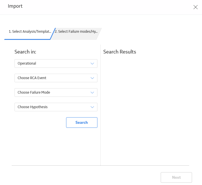
- Select Search.
The analyses and templates that meet the specified criteria appear in the Search Results subsection. For each analysis, the label that appears in the search results is the value in the Analysis Name field in the Root Cause Analysis record for that analysis.
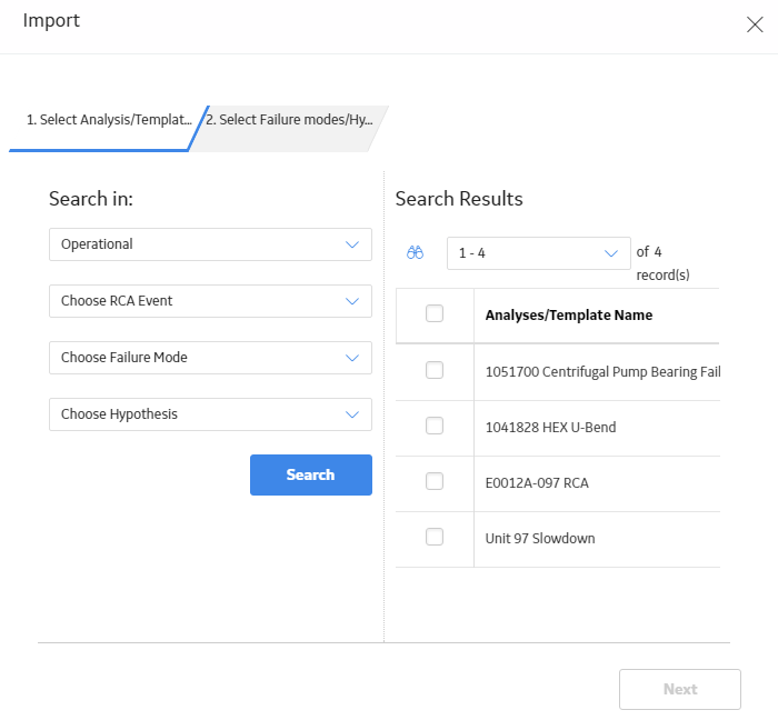
- In the Search Results subsection, select the check box in the row for each RCA containing Failure Modes and Hypotheses that you want to import, and then select Next. Note: Although you can select the check box in the row for an RCA, you cannot import an RCA into the Logic Tree.
The Select Failure modes/Hypothesis section appears, displaying a list of RCAs.
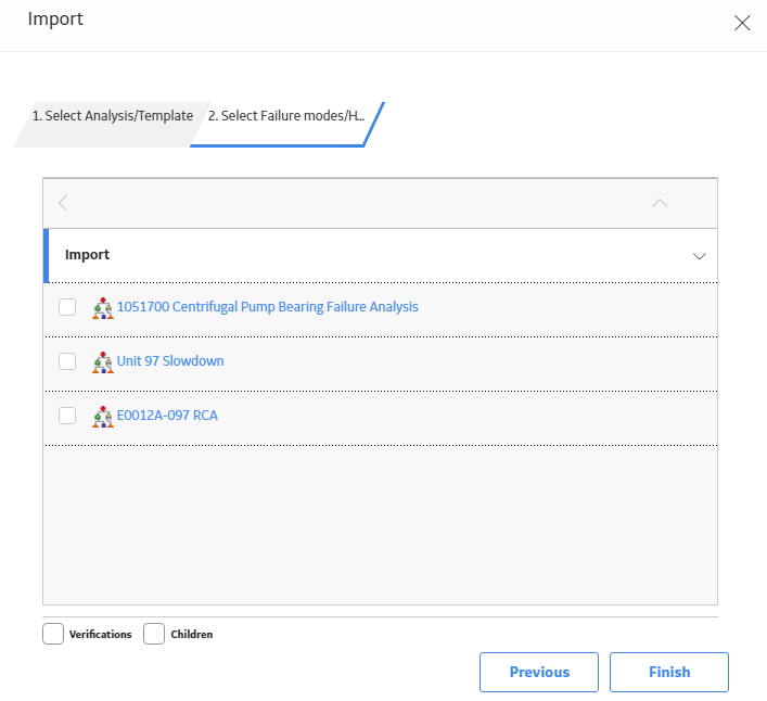
- Select the check box next to each RCA Failure Event that you want to import, and then select Finish.Note: The Verifications check box is enabled only if you import a Hypothesis. If you want to import the RCA Verifications associated with the selected Hypothesis, select the Verifications check box. The Children check box allows you to import a selected node and any associated children.
The Import window is closed. The Logic Tree workspace appears, displaying the newly added Failure Mode or Hypothesis to the Logic Tree diagram for the selected analysis.
Results
-
If you import an RCA Hypothesis along with the linked Verification, a new Verification is created and linked to the Hypothesis that is created from the imported Hypothesis. Values from the following fields in the Verification are copied to a new RCA Verification:
- Method
- Send Alert on Due Date
- Alert Email Text Fields
Import Failure Modes from Failure Modes and Effects Analysis (FMEA) and Reliability Centered Maintenance (RCM)
About this task
Procedure
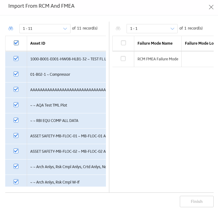
- At the top of the workspace, in the Manage Diagram section, select , and then select Import From RCM and FMEA.
The Import From RCM and FMEA window appears, displaying a list of assets that are linked to the analysis.
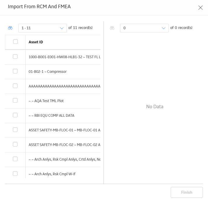
- Select the assets containing Failure Modes that you want to import.
A list of Failure Modes linked to the selected assets appears.
Arrange Nodes Manually Within the Logic Tree
About this task
If you manually arrange nodes, the arrangements are saved. The GE Digital APM system only automatically arranges the presentation of the nodes of the Logic Tree diagram in the design canvas when the Auto Arrange option is enabled.
Procedure
Delete Nodes from the Logic Tree
Procedure
- In the upper portion of the workspace, select
 .
.The Delete Logic Tree Items dialog box appears, asking you to confirm that you want to delete the selected node and its successor nodes.
Results
- All the child nodes of the deleted node are deleted.
- The link between the deleted node and the node to which it was linked is removed.
Export a Logic Tree Diagram
About this task
You can export a Logic Tree as an image and save it to another location, such as your local hard drive.
Procedure
- At the top of the workspace, in the Manage Diagram section, select
 .
. The Save as window appears.
Add a Hypothesis to a Logic Tree
Before you begin
Procedure
- In the upper portion of the workspace,
in the Palette section, select .
- Select .
The Hypothesis appears in the Logic Tree diagram.
Results
- A link is created between the Hypothesis and the RCA. A link is also created between the Hypothesis and either the RCA Failure Mode or the predecessor Hypothesis.
What to do next
Add a New Hypothesis to the Hypothesis List
About this task
A Hypothesis List contains a list of Hypothesis that have been defined by an RCA Team. During an RCA team's analysis sessions, ideas are proposed quickly. The Hypothesis List page provides a quick method for capturing these ideas without having to add Hypothesis nodes directly to the Logic Tree diagram. Any hypothesis that is added via Hypothesis List pane can be added as a Hypothesis node to the Logic Tree diagram.
Procedure
- In the lower-left corner of the workspace, select the Hypothesis List pane.
A list of Hypotheses available in the database for the selected RCA appears.
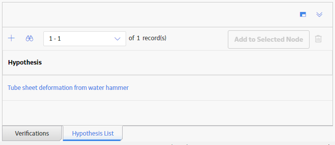 Note: If any RCA Hypothesis are linked to the current RCA but do not appear in the Logic Tree, they will appear in the list.
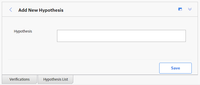
 - Above the list, select
 .
. The Hypothesis box appears.
Add a Hypothesis from the Hypothesis List to the Logic Tree
Before you begin
-
Make sure that the Hypothesis List pane contains a Hypothesis that you want to add to the Logic Tree.
-or-
- Add a Hypothesis to the Hypothesis List
Procedure
- In the lower-left corner of the workspace, select the Hypothesis List pane.
A list of Hypotheses available in the database for the selected RCA appears.
Note: If any RCA Hypothesis are linked to the current RCA but do not appear in the Logic Tree, they will appear in the list. - In the upper-right corner of the pane, select Add to Selected Node.
The new Hypothesis node appears on the Logic Tree at the specified location.
Note: As needed, you can modify the Hypothesis node. To do so, select the Hypothesis, and then select to view the datasheet for the added Hypothesis. As needed, modify the available fields.
Change the State of an RCA Hypothesis
About this task
When an RCA Hypothesis is created, the state is set to Hypothesis by default. Based on the Verifications, each RCA Hypothesis can then be tested and proven True or Not True, and then you can change the state of the Hypothesis accordingly.
Procedure
- In the design canvas, select the Hypothesis whose state you want to change, and then select .
The Properties window appears, displaying the datasheet for the selected node.
Note: You can also change the state of a Hypothesis from the States panel. To do so, select the Hypothesis, and then select .
. - Select .
The State of the Hypothesis is saved.
Identify the Root Cause for Hypotheses Proven True
Procedure
- In the design canvas, select the Hypothesis for which you want to specify the root cause, and then select .
The Properties window appears, displaying the datasheet for the selected node.
Note: You can also change the state of a Hypothesis from the States panel. To do so, select the Hypothesis, and then select. - Select .
Your changes are saved.
Results
After you select a cause:
- A red line is drawn to show the path to failure.
- The icon used to identify the Hypothesis node changes to indicate the specific cause.
- The team can communicate their findings to the decision makers in your organization.
Delete a Hypothesis from the Hypothesis List
Procedure
- Select the Hypothesis that you want to delete, and then select .
A dialog box appears, displaying a confirmation message.
Access a Verification
Procedure
- In the lower-left corner of the workspace, select the Verifications pane.
A list of Verifications that are available for the selected Hypothesis node appears.
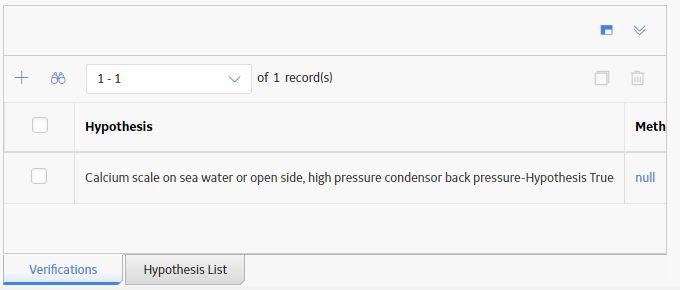
- In the Method column, select a Verification whose details you want to view.
The datasheet for the selected Verification appears.
Note: As needed, you can modify the values in the available fields, and then select to save your changes.
Add a Verification to a Hypothesis
Before you begin
Procedure
- In the lower-left corner of the workspace, select the Verifications pane.
A list of Verifications that are available for the selected Hypothesis node appears.
- Above the list, select . Note: RCA Verifications are associated only with RCA Hypothesis. If you do not select a Hypothesis node in the Logic Tree, an error message appears, prompting you to select a Hypothesis to add a new Verification.
The Create Verification pane appears.
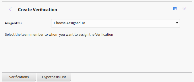
- In the Assigned to list, select the team member to whom you want to assign the Verification.
A blank datasheet appears.
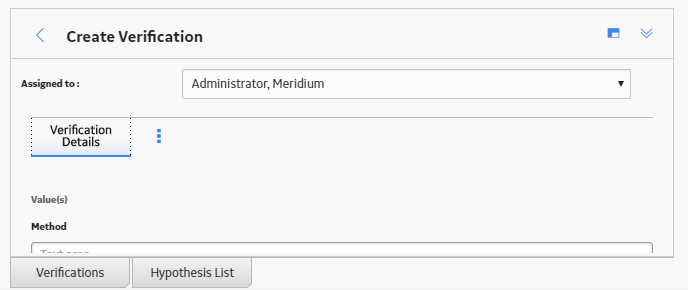
- Select .
The RCA Verification is saved and linked to the RCA and the Hypothesis.
Results
What to do next
Copy a Verification
About this task
This topic describes how to copy a Verification. You can also add a Verification node to the Logic Tree from the design canvas.
Procedure
- In the lower-left corner of the workspace, select the Verifications pane.
A list of Verifications that are available for the selected Hypothesis node appears.
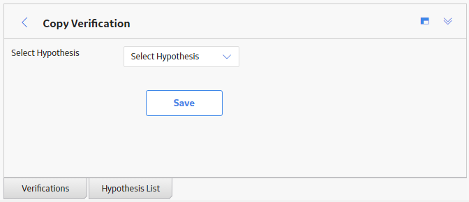
- Select the check box to the left of the Verification that you want to copy, and then select . Tip: You can copy more than one Verification.
The Copy Verification pane appears.
Delete a Verification
Procedure
- Select the check box to the left of the Verification that you want to delete, and then select
 .Tip: You can select more than one Verification to delete.
The Delete Verifications dialog box appears, asking you to confirm that you want to delete the selected Verification.
Enable Logic Gates
Procedure
- At the top of the workspace, select, and then select Show Logic Gates.Note: If the Show Logic Gates option is enabled, a check mark will appear to the left of the option.
The Logic Gates appear in the design canvas.
Add a Logic Gate to the Logic Tree
Before you begin
Procedure
- In the upper portion of the workspace, in the Palette section, select or , and then use the drag-and-drop method to add the Logic Gate in the design canvas to a node.
The Properties window appears, displaying the datasheet for the selected Logic Gate.
- Select .
The Logic Gate is added to the Logic Tree.
Results
A link is created between:
- RCA and Logic Gate.
- RCA Logic Gate and the records associated with the node to which you added the Logic Gate node.
What to do next
Change the Gate Type of a Logic Gate
Procedure
- In the design canvas, select the Logic Gate whose Gate Type you want to change, and then select .
The Properties window appears, displaying the datasheet for the selected Logic Gate.
Note: You can also change the Gate Type from the States panel. To do so, select the Logic Gate, and then select .
. - Select .
The Gate Type is updated.