2022 AM Industry Summit

The AM Industry Summit brings together the global additive manufacturing aerospace and energy industries for a unique, hands-on, interactive event. Discover the latest materials, metals, and polymers, while uncovering design and technology solutions across the AM and 3D printing industry.

June 20-22, 2022
Long Beach, CA

Booth 19

Convergence of AM Aerospace and AM Energy

Join GE Additive at this year’s AM Industry Summit, a convergence of AM Aerospace and AM Energy. This conference brings together the global additive manufacturing aerospace and energy industries for a unique, hands-on, interactive event. Discover the latest materials, metals, and polymers, while uncovering design and technology solutions across the AM and 3D printing industry.

  • Visit us at booth 19 to see the innovative parts we will have on display and talk to an additive expert.
  • Attend our presentation: M Line and Ni718 - Enabling metal additive production through stability and stitching; Presenter: Sarah Ulbrich, GE Additive; June 21, 4:30 – 5:00 p.m.


Can’t attend in person? Check us out on July 13 during Virtual Day. You can access on-demand content from the live conference as well as the presentation Additive Manufacturing and GE Aviation’s GE9X Engine, during which GE’s Chris Philp will show the various additive parts that are included on the latest commercial engine.

Click here for more information on the show and to register for the live and virtual events. Use promo code AMSPN25 to save 25% off your conference pass.

AM Summit
August 02, 2018
Join us in Long Beach, CA, for the AM Industry Summit
Trending
Off
Featured
Off
Date for view sort
Thumbnail image
AM Summit
Latest case study
Off
Webinar Category
Highlighted Stories
Off

Profile: GE Additive Lichtenfels Process & Materials team

We recently caught up with the GE Additive Lichtenfels Process & Materials team to learn about their focus and recent work on aluminum parameters.
 

We recently caught up with the GE Additive Lichtenfels Process & Materials team to learn about their focus and recent work on aluminum parameters.

Tell us about the team

We currently have 15 engineers in our team at the new GE Additive Lichtenfels facility, locally known as the 3D Campus. Local is the keyword here. In fact, most of our team graduated from universities in the local area. A combination of different skill sets and disciplines, including materials engineers, process engineers and mechanical engineers mesh well to help us solve the diverse tasks we’re charged with.

As for our day-to-day right now, our biggest focus is on parameter development, where we fine tune and adjust the machine settings of our additive machines, like the laser power or scan speed, to get the perfect part outcome for the different materials we process. We get involved in customer projects in either a consultative capacity or working on specific parameter development. We also support our production and service teams by troubleshooting any issues that might occur.

As part of the GE Additive Global Materials & Powders team, we take part in weekly tech forums. This exchange helps us tap into all the expert knowledge from around the world and share our own experiences. Ultimately, this helps us all drive the best outcomes on the various projects we are all involved in.

We are also regularly involved in initiatives across the other GE businesses. We currently have multiple projects running concurrently with GE Aviation, focused on tailoring parameter sets, and projects with GE Global Research (GRC), which are focused more on the additive technology process, rather than the end-product.

Can you share more on the team’s work on processes and parameters?

Think of our team as organized into two parts. The first is the process part where the engineers work closely with the machine teams – for example the gas flow, optics and software teams – to understand how the characteristics of those systems drive the final part performance. We also support tasks such as specification definition, so whenever a new component is developed, we need to give our input from a process perspective. We then get involved with the design and consulting phase and the validation phase for either new machines or new subcomponents within a machine.

The other side is the materials part where we investigate how the laser parameters affect the microstructure of the material and tailor parameters to meet our customers’ requirements, like porosity, microstructure or mechanical properties.

When we combine these aspects and use the input from both groups of experts, this enables us to guarantee best part quality and material performance.

The team’s work on aluminum parameters has gained a lot of interest and praise from across the industry. Why is that?

We have quite a large parameter portfolio for aluminum alloys, which was even increased and improved by the most recent work and latest parameter developments. Work on aluminum parameters was done on all types of machines. Two projects were running for the AlSi10Mg, one on the M2 Series 5 and one on the X Line 2000R. The outcomes of these projects are high-quality parameter sets for this alloy.

Another project worth mentioning on the M2 was initiated to develop a high-productivity parameter set for AlSi7Mg. In the end we were able to more than double productivity compared to the previously available parameter set by increasing layer thickness from 60 to 90 µm and using the full 1kW capability of the machine while keeping part properties on a similar level.

Beyond these core alloys, we are also working on the high-strength alloy A205 for elevated temperature applications. We just recently released a parameter for our M2 machines, and we are currently at the stage of transferring the processes and parameter sets to our new M Line solution to get this material running well on that new system.

The team in Lichtenfels has historically been focused on laser technology. Do you also support our other modalities?

As we briefly mentioned, as a materials community we all come together in our regular tech forums to exchange ideas and knowledge. Being focused on the laser business, we have our own perspectives; however, whenever there are tasks to solve from a material point of view, it is always good to get an outside perspective. If we are working on material-specific problems or projects, such as heat treatment developments and microstructure evolution investigations, the modality is less important than the fundamental materials science knowledge, so we regularly speak with the EBM and Binder Jet teams to facilitate this materials science-focused crosstalk.

Can you tell us about the set-up of your new labs, and the on-site testing and analysis technology at your disposal?

There are three labs here at Lichtenfels:

  • The metallographic lab is where we do the cross sectioning and the etching (to visualize the melt pool shapes). We have several optical microscopes and one scanning electron microscope equipped with one EDS (energy dispersive X-Ray spectroscopy) and one EBSD (electron backscattered diffraction) sensor, which we use to do in-depth characterizations on the phases and chemical composition of a material.
  • The mechanical lab – where we do the tensile, hardness, and surface roughness testing (optical and tactile) – enables us to execute all the required standard testing methods. We also have one CMM (coordinate measuring machine) to check dimensional accuracy of parts. 
  • We also have a completely new powder lab where we can do almost everything related to powder characterization—from particle size distribution by laser diffraction to sieve analysis, flow testing and rheology testing using flowmeters. We built a special powder test rig to investigate the spreading and packing behavior of the powder to determine how the powders will behave in our machines. We also have the capability to analyze the chemical composition of powders and parts for different gases—including oxygen, hydrogen, nitrogen—as well as the carbon and sulfur content.

These new advanced material characterization capabilities are needed to satisfy the needs of our customers

GE Additive Lichtenfels materials lab - November 2021

What value do in-house analysis capabilities bring to our technology and to our customers?

We do everything in-house, from sample preparation to characterization and heat treatments, and this reduces the lead times dramatically. Instead of weeks of turnaround time when using external labs, we are talking about a few days to get the results out of our own lab. In addition to the time benefit, it also significantly reduces the administrative effort required by the team.

The quick turnaround times are even more important for issues that might occur in production or in the field. Instead of sending samples away and waiting for an answer, we are able to immediately address issues when they come up.

Another aspect is cost. It is costly to perform metallurgical investigations, so by having direct access to the person doing the analysis and being able to influence how the samples are analyzed, you can really cut back on both time and cost compared to sending the samples to a vendor. This is extremely helpful as it not only accelerates but also improves the outcome of the analysis.

What gets you excited about materials science and additive?

Dominic Graf: The variety of work. We are not only directly developing different parameters, but we also collaborate closely with a lot of other departments of the business, like hardware design or software development across our portfolio of machines. I believe our wider Global Materials & Powder team is the link between the different R&D teams. We work with them to finish any development on our machines, we are also the first testers of new developments, and provide feedback regarding the changes and potential impacts on the process.

Essentially, our job is to improve the different additive manufacturing processes and machines so that we can ensure a high part quality. We do this by having that regular exchange, collaboration, and interaction with other engineering departments to generate different ideas and solutions to the challenges that present themselves each day. And there are still so many open opportunities to investigate or to improve, which makes our daily work so fascinating.

Daniel Rommel: One of things that is motivating for most tasks that we get is that we often do not have a solution immediately available. It’s our job to think about it, test, create and present a solution.

For me, that is more inspiring than simply getting a task assigned where you already know what to do. Here in Lichtenfels we are really focused on creating solutions for specific customer requirements, and that is both motivating and fascinating for the team.

Johannes Stroessner: I find it extremely helpful to get a connection to the product through a “touch and feel” experience. With the direct contact with what the machines are producing, we get direct feedback on how our developments impact the overall result. So, whatever you change, you directly see the outcome of the continuous improvements we make and, in turn, how it helps customers either improve the quality of their parts or produce them faster. 

It’s very easy here to make a tangible link between the materials science and our machines, and then eventually a connection to the end-product, and that is a very rewarding part of the job.

Overall outlook

The Lichtenfels team is a core part of the global materials organization within GE Additive that understands the whole additive process chain—from the powder through to the final part.

The diverse backgrounds, knowledge and skills within the team, coupled with new analytical characterization capabilities and a link to GE’s wider material science expertise, enables the Lichtenfels team to support both customer engagements as well as internal GE initiatives to facilitate the best possible outcome.

If you’d like to learn more about the Lichtenfels team and the wider GE Additive materials community, please get in touch
 

GE Additive Lichtenfels process & materials team - November 2021
November 10, 2021
Trending
On
Featured
On
Date for view sort
Thumbnail image
GE Additive Lichtenfels process & materials team - November 2021
Latest case study
Off
Industry stories
Highlighted Stories
On

Get the Facts on… Alloy Selection

Regardless of whether you are completely new to metal additive manufacturing, have already made some prototype designs or are an advanced user of the technology, choosing the right alloy for your part can be a daunting task…

Regardless of whether you are completely new to metal additive manufacturing, have already made some prototype designs or are an advanced user of the technology, choosing the right alloy for your part can be a daunting task—especially if you are looking to using a completely new alloy for your component. However, the process doesn’t have to be overwhelming. Mike Baughman, materials engineer at GE Additive, explains.


Mike Baughman

At what point should additive users start thinking about alloy selection?

That is usually influenced by the additive modality they are looking at, but I would say that you should be aware of the alloys that are currently available. Because additive technology is relatively new, we don’t yet have the breadth of alloys that are used in conventional manufacturing. Users should be aware of what currently exists today, especially if they are not looking to run a material-development program.

The first step would be to identify the additive modality for the intended application and be aware of what materials currently are developed as commercial offerings, especially if they are not looking to run a materials development program.

However, while you should be aware of the alloys, you don’t need to be concerned about making parts from a specific material if you’re just starting your additive journey. You need to first think about the function of the design and what you need the component to do, rather than what it is going to be made of.

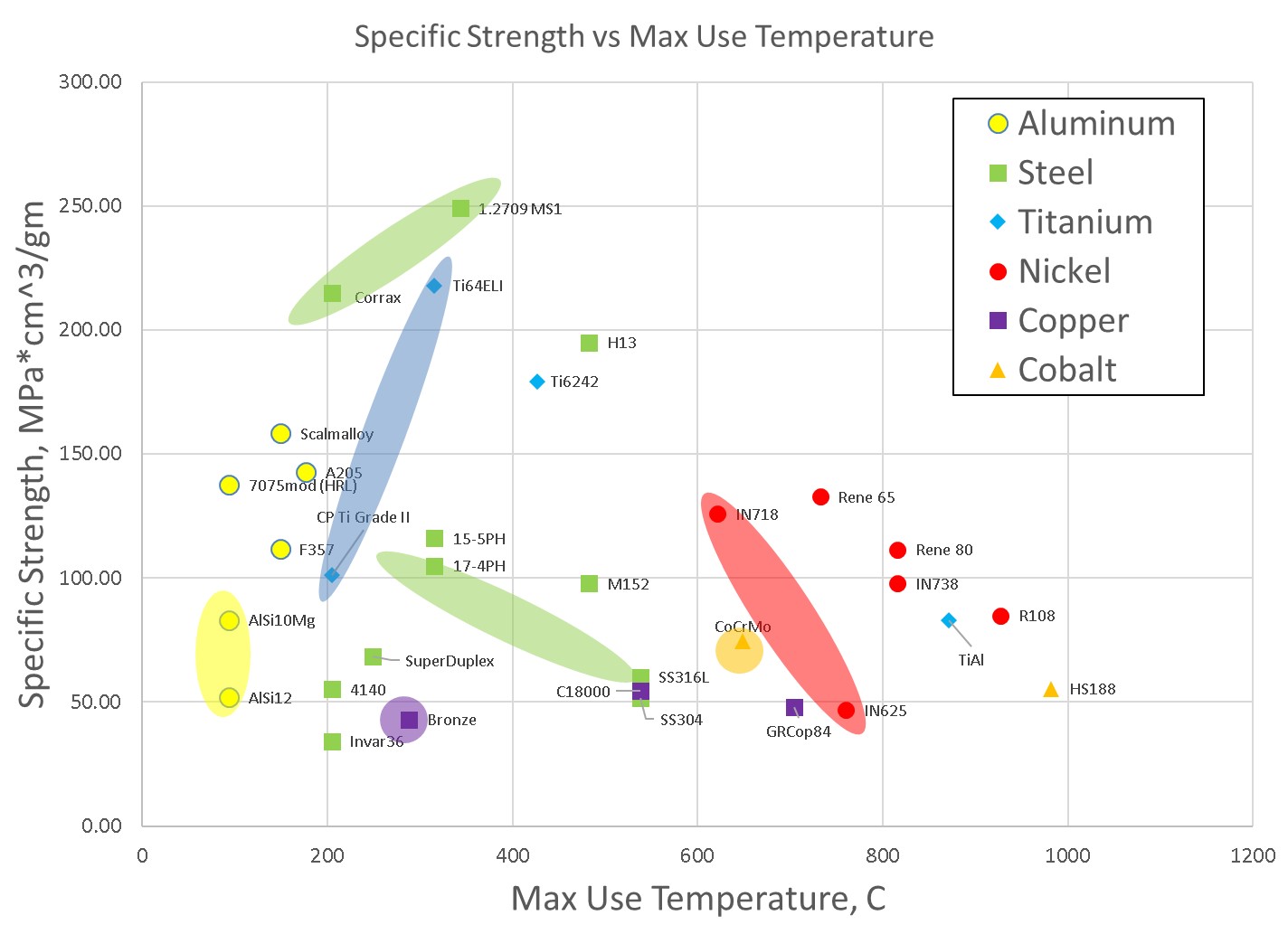
Once a customer starts to understand the needs and constraints of their part, we can start to help them down select to an alloy family and look at the specific needs that will guide them through the alloy selection process. For example, operating temperature requirements will help us down select massively, because there are only certain alloys that operate in higher temperatures, and there are more cost-effective alloy options available for lower temperature applications.

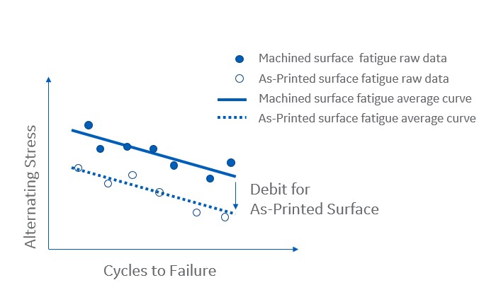
As a customer’s part design develops further, we can start to think about the operating environment of the component and the key properties needed, such as tensile strength, fatigue, and corrosion resistance. Once we establish the functional part requirements, we start to get a clearer indication on which alloy might be best.

How is alloy selection in additive different to conventional manufacturing?

One of the things that customers often realize quickly is that there is still a limited amount of data for additive manufacturing alloys. While there may be very good data sheets and well-thumbed handbooks for alloys in conventional manufacturing, such as casting and for industry-specific sector applications—for instance in aerospace—these material databases don’t yet exist for additive manufacturing materials.

So, early on in the design process, customers can sometimes get hung up on wanting data that hasn’t been generated, and the absence of data is something that many people, particularly engineers, are not used to—especially if they have been using the same materials for many years.

Work is ongoing to build these databases for additive. In the meantime, it is possible to leverage existing property databases of different alloys to help down select when we don’t have the specific additive manufacturing data in front of us.

Is there an opportunity to write, or rewrite, the handbook on alloy selection?

There are two paths to talk about here. The first is the materials pathway, and designers today really need to hit the reset button and look at what materials are available today and the opportunities that additive manufacturing offers.

With additive you can throw out many design assumptions that you previously had to envision and create more complex and customized geometries. I would put materials into the same line of thinking as well.

If you’re redesigning a new part using additive, you’re not only going to remove the need for machining, but you can also step back and realize that you don’t need to make these parts out of the same material that you have been doing for years.

If you start designing the part for the functionality it needs, then you can understand what you need out of your material, and what you might have previously thought was your optimal material may well be different once you’ve gone through that redesign process.

It all comes down to you driving towards the additive manufacturing alloy that is right for you.

Do those alloy handbooks and previous experience lead additive users to make assumptions about alloy selection?

There’s an assumption that customers need to have their legacy material to be able to do additive. Our team has been asked on many occasions if we have a certain material available for additive, and when we don’t, they believe that additive simply won’t work for them. We need to break down this assumption, because you can do it. You just need to work out how you can get there rather than fixating on a particular material.

Another assumption is that there is a barrier to additive manufacturing because of a lack of property data, and if it’s not available in a handbook, customers think that they can’t design a component.

As I mentioned, there are ways to work around this, and this is one of the ways GE Additive supports and adds value for its customers. From materials development to characterization, we aid in the design and offer our expertise to help generate any property data that is required.

In many cases, the barriers are not as big as people believe, as it’s often isolated data points that need to be found, such as tensile data or a specific fatigue design point.

Do designers always want to know about material properties straightaway, or are they thinking about the part, the end application or the machines first?

It varies from customer to customer and often depends on their previous exposure to additive. Some customers come in with an engineering mindset, others with a design mindset, while others come in with preconceived notions about additive. When we talk about additive, we refer to the entire additive ecosystem: the materials, the powder, the machines and the processes, which individually and collectively are all important.

Of course, the machine is important, but equally so is the material-process property relationship, and you need all these things if you wish to get the properties that you need for designing and manufacturing parts with consistent capability. No one aspect is more important than the other, as they are all related and all of them are critical.

So, if you choose to focus on the performance of the machines but neglect the other aspects (a robust process and the right materials developed), then you’re never going to get to designing parts or manufacturing parts in high volumes.

What are some of the practical steps to alloy selection?

When a customer is first starting their additive journey and trying to hit that reset button, come up with a design—and take advantage of additive’s design freedoms—you don’t need to be thinking about material properties at this point. When you’re starting to run analyses on your parts, and you know what environment(s) they’ll be operating in, you’re already starting that down selection process.

Designs will typically fall into two camps. The first will give an additive user good functionality and they will be able to make it work with an existing material. The second approach is more revolutionary, and users will need to go out and invest time and money to develop the material to enable this design because it doesn’t exist today.

One thing to note with either approach is that, because we don’t have thousands of alloys in the additive manufacturing portfolio, users might not find the optimal material. However, with the design flexibility possible with additive, customers can almost always produce something that’s better than the conventional product.


Ashby Chart


How does GE Additive help customers find the right material for them?

Depending on the customer’s needs, we have the capabilities to help them all the way from the beginning to understand what additive is, how to design for it and what the capabilities of additive are, through to material development and characterization, and all the way to industrialization and setting up a production factory.

A lot of it depends on the customer’s baseline understanding of additive when they come to us. So, for a customer who has already been doing some prototyping and already has a design in mind, we can help them in developing the material property data and process that will help them industrialize.

No matter the starting point, the customer’s journey pulls in different aspects of our team’s expertise, from materials characterization to the process experts in each modality, as well as our specialists who can help to design an alloy that can optimized for additive manufacturing and/or possesses specific material properties.

Across the wider GE family, we have a deep seam of materials knowledge that we can leverage. We’re more than a machine manufacturer. We also look at the whole ecosystem of additive—from a manufacturing approach, a machine design approach and the process development qualification that is required for the heavily regulated industries we operate in. 

We also have an AS9100-certified production facility in the US for aerospace manufacturing, so our work spans many areas, from process development and machine creation, all the way through to producing parts and hardware.

Is there a need for more industry standardization (ISO, ASTM)? What role do industry standards/standards bodies play in the role of alloy selection?

We’re starting to see some standards being put out by major organizations, such as SAE, ISO and ASTM for a few alloys and modalities. There is a lot of work on standards in the laser space, and again, we’re starting to see specifications for some alloys, such as Ti6Al4V.

So, in the industry standards area, things are maturing, and discussions are ongoing to develop those specifications across laser, EBM and binder jet. Some are in the early stages, though, so there is still a lot of variability.

Overall outlook

While additive might seem daunting to companies who are used to having everything they know at their fingertips, in the form of industry handbooks and data sheets, it is important to discard any preconceived notions about additive and reset your way of thinking in order to harness its full potential.

Once you discover that additive could be an option, users of the technology experience a redesign process that will provide the right alloy for each intended application and much better design freedoms than is possible with conventional manufacturing methods.

Working with industry experts, like GE Additive, can not only help to guide you through the development and redesign process, but it will help you to understand the needs of the whole additive ecosystem and find ways of obtaining any necessary data that you need for your part. 
 

If you’re at any stage of additive development and design, or want to know more about it, please contact us.

Alloy selection - Ashby chart - GE Additive - October 2021
October 05, 2021
Trending
Off
Featured
On
Date for view sort
Thumbnail image
Alloy selection - Ashby chart - GE Additive - October 2021
Latest case study
Off
Industry stories
Highlighted Stories
Off

Get the Facts on… Curve Generation

Generating material data is an advantageous endeavor, regardless of whether you are looking to use additive or conventional manufacturing methods…

Generating material data is an advantageous endeavor, regardless of whether you are looking to use additive or conventional manufacturing methods. The right type of data can tell you a lot about your material and how it will behave in different application environments, but the way we obtain material data for additive can sometimes be different from conventional manufacturing (although they do share some similarities as well). 

We caught up with Kelsey Rainey, materials engineer, to discuss how data is generated for additive parts and some of the key pointers when comes to obtaining the right type of data.

What is the relationship between alloy selection and curve generation?

Overall, alloy selection helps how you approach the curve-generation process. For example, if you’re interested in nickel alloys, then you’re going to need to consider testing at temperatures above 1000°F. However, if you’re working with aluminum, the tests are going to be more in the low to mid hundreds of degrees F. So, the choice of material is going to change the approach you’re choosing for curve generation and the way that you approach creating your test matrix.

Once you select an alloy, that choice is going to drive the component development. Alloy selection and curve generation is a big intertwined, iterative process. On one hand, you may know what your component is and you’re looking for a material that works, but on the other hand, you may already know a material that works and you’re trying to pair that material with a suitable component. By combining the need for alloy selection and curve generation, it’s going to help drive what you need to test, the field conditions your component will see and what kind of data you need to capture to address that.

What are some of the assumptions additive users make about curve generation?

There are two misconceptions that we regularly encounter. The first is that material property curves are just math. Some users believe that you come up with the test matrix, send the bars off to get tests and the data that you receive is plugged into the computer and your curve is ready to go and design toward. However, at GE Additive, we approach curve generation as a combination of statistical analyses and engineering judgment. Pure statistics can tell us one thing but having engineering experience with certain alloys and test conditions can pick out points in the statistical analysis that might not tell the whole story. You need to marry both approaches before creating your final curves.

The second misconception is that you can generate the material property curves faster with additive than conventional manufacturing methods. In additive manufacturing, there is often a push to get things done faster and reduce time and cost. But when it comes to testing, it’s not always that simple. For many tests, there is a limit to how much you can reduce the time spent. Take creep testing for example. A common creep test is a thousand hours long, and that test will run for the full thousand hours, regardless of whether you’re doing additive or a conventional manufacturing method. Testing takes time and cost investment, and there are only so many places where you can realistically cut down your timeframe.

How do you make a curve and how do additive curves differ from the curves generated for conventional materials?

There are two main approaches to generating material property curves. One way is to take an existing equation and fit your data to that equation. One example is the Coffin-Manson equation, which can be used to fit fatigue data.

We approach curve fitting from a regression analysis perspective. So, we’ll develop a test matrix, test the bars, get raw data points back and fit the data using regression analysis. We look at the data using a few different regression fits, and then we’ll combine those regression fits with our engineering judgment to determine what the final curve will look like. We also have several different criteria for determining whether or not the fit of the data is good.

The additive manufacturing curve generation process is similar to those implemented for conventional materials; however, the big difference comes when you start to look at what independent variables you need to consider. Once a component has been selected, or we at least know what environment the material will be in, we create a test matrix that consists of different property tests across a range of temperatures.

This is where the process starts to differ. In conventional materials, the independent variables you would typically consider are temperature, grain orientation and material heat/lot. In additive manufacturing, we want to consider these variations as well, but they present in different ways. For example, with grain orientation, rather than capturing bars oriented differently within an ingot like we do with conventionally manufactured material, we print bars horizontally and vertically on our print bed to capture any material dependence on orientation. We also need to consider how we’re capturing chemistry variations in our powder and variations across the build plate. 

There are different independent variables that we now need to consider in additive that we wouldn’t have to consider in conventional materials, but the general process of taking the test data and generating the curves from that remains essentially the same.

Speaking of variables, what are some of the end-use variables that you need to consider?

One of the questions we get asked frequently is about the type of data collected. There is a baseline set of tests that we would perform if we wanted to develop a material, but there’s no specific component in mind. Once you have your alloy family, we can then tailor the tests. For example, we always run a tensile program and fatigue testing for nickel and aluminum, but the test conditions (temperature for example) will vary depending on the material selected.

Tensile and fatigue tests are the two main tests, so even if there’s no specific component in mind, we will nearly always do some variation on those tests. Once the component has been decided, that will then drive further tests based on the intended environment. The more specific and detailed test programs start to get fleshed out as we figure out what a customer’s component is going to see in the field. The test matrix becomes much more specific and tailored to specific component requirements when the customer can understand what the component is going to see, which will ultimately drive what kind of testing you will do.

How much data, and what type of data, do you need to make a curve?

It ultimately depends on how you want to use your curves and whether you control your process or not. At GE Additive, we make sure that we control our process and put limits in place to make sure that our process is stable (stable parameter sets, materials specification and machine specification). If those steps are complete, and the process is controlled, then there’s not a massive amount of variation in our test data, so you might not need as much data as you might think.

If you don’t have a stable process, don’t have a locked parameter set or if you’ll be testing across different machine types, then you will need a lot of data to ensure that you have a statistically significant quantity of data to create curves. This can get prohibitively expensive, and quickly.

However, if you have those controls in place, obtaining the required data is much more cost efficient and economically achievable. So, it’s a better use of time and resources to first control your process and understand the limits on that, and then generate your data.

Curve generation chart


The quality of the data is also important as well, isn’t it?

It is. The most important thing to consider when collecting data is controlling the process, followed by understanding and capturing all the pedigree information. Pedigree information in this context would be anything that could impact your test results. This might be from the powder lot to the location on the build plate, the parameter set you used to build the bars or where the bars were treated, tested and/or machined. You want to have a clear traceability to all this information, because data without pedigree is worthless. So, the quality of your data is important. By controlling your process and maintaining traceability of the pedigree of all the bars, you will get quality data points.

What can data and curves tell us about as different material properties, such as surface roughness, as-printed surfaces, or fatigue results?

There are many ways to characterize your surface—from optical to tactile measurements—but the curve generation and test data are great ways to quantify what effect that surface has on your material. You can spend a lot of time in the lab coming up with the actual roughness of a surface, and while those values are useful to know, they don’t tell you what impact that has on the properties of your material. So, by undergoing a range of surface-specific testing programs, we can quantify these values if a customer has an as-printed surface on their component. 

These testing programs can tell us what is going to happen with parts, and you can then life your parts that have as-printed surfaces. This is important from an application perspective as you can take the characterization of the surface and put a quantifiable debit on what you can expect from a machined surface compared to an as-printed surface.

Curve generation group


Overall outlook

Generating data curves for your materials and components can be a much simpler and economically viable option if you have your process controls and characterizations in place first.  If you have these controls in place, you have all your pedigree data, and you have considered the additive-specific independent variables, then you don’t need to obtain as much data as you might think. 

There are different approaches to generating material data curves, depending on both the material/component itself, where the part will be used and where a user is in their additive journey. 


If you’re at any stage of additive development and design or want to know more about it, please contact us.

GE Additive Curve Generation_October 2021
October 12, 2021
Trending
Off
Featured
On
Date for view sort
Thumbnail image
GE Additive Curve Generation_October 2021
Latest case study
Off
Industry stories
Highlighted Stories
Off

Get the Facts on… Heat Treatment

Heat treatment cycles are used in the manufacturing process of functional and mission-critical parts, regardless of whether they are made by additive manufacturing or by more conventional manufacturing methods…

Heat treatment cycles are used in the manufacturing process of functional and mission-critical parts, regardless of whether they are made by additive manufacturing or by more conventional manufacturing methods. However, while there are many similarities between the steps additive users need to take to heat treat their parts, there are also some marked differences compared to conventionally manufactured parts.

We caught up with Lyndsay Kibler, lead materials application engineer, and Sean Kelly, staff engineer, to find out more.  

Lyndsay Kibler & Sean Kelly

What are some of the typical heat treatment steps for metal additive parts, and why are they necessary?

The main goal of heat treatment is to stabilize the metallic microstructure and balance material properties. The types of heat-treat cycles used vary depending on both the alloy and fabrication method, but all of them play an important role.

For laser powder bed fusion (L-PBF), residual stresses are created in parts due to the rapid melting and cooling of each layer, so a stress-relief cycle is necessary to reduce distortion before removal from the build plate. Depending on the alloy used or part application, you might also want to perform a hot isostatic press (HIP) treatment to maximize density and create a more isotropic microstructure, and consider solution and age cycles for applicable alloys.

By comparison, electron beam powder bed fusion (EB-PBF) has a hot powder bed, so the stresses that are induced in L-PBF are not necessarily found in EB-PBF parts, meaning stress relief treatments are not needed. The alloy and/or application may still necessitate HIP or solution and age cycles though. 

Binder jet is also different. Because this modality doesn’t melt powder in the powder bed, a new type of heat treatment is employed: sintering. This process first burns away the binder and then consolidates the particles by solid state atomic motion. A sinter step takes a 50-60% dense “green” part from the printer and creates a solid part which is greater than 99% dense.

Solution and age cycles can be used with the various additive modalities to strengthen those alloys. Solution cycles are most applicable for solution-strengthened and age-hardenable alloys. An age cycle is performed after the solution cycle for age-hardenable alloys. This lower-temperature process allows the strengthening phases to precipitate in a controlled manner.

Nickel Alloy Example

How does heat treatment with additive manufacturing differ to conventional methods?

The difference between additive manufacturing and conventional manufacturing methods is not as different as you might think. The main difference with additive is that you have to consider how the part is made, more so than you do with conventional methods.

For example, L-PBF goes through a stress-relief process, which would be the same as a conventional post-machining stress-relief heat treat. With binder jet, you’d go through the binder burnout and sinter steps. And the high inherent process temperatures of EB-PBF mean that the parts don’t require any additive-specific steps. For all these modalities, once you’re at these points, the processes and steps are then no different from conventionally manufactured parts. You’re still dealing with the same chemistry and the same overall microstructure of the part, it’s just that the microstructure in the part is set at a different stage of the manufacturing process.

Why don’t all alloys use the same heat treat cycles?

The goal of heat treating a part is to set the microstructure and balance material properties. Each metal alloy has a different composition of elements that results in a different overall chemistry, and this means that the “stable microstructure” looks different in each alloy. The variation in chemistry means that different metallic phases form at different temperatures and rates. Some of these metallic phases require more time at temperature than others, so the heat treat recipes need to be set at different temperatures and held for different times to best suit the chemistry of each alloy. It is the balance of these metallic phases that generates desirable material properties in your alloy.

How do you verify if a heat-treat cycle was run successfully?

There are several tests that can be performed on a heat-treated material to verify that the desired material properties were achieved. Most commonly we take samples from the heat treat run, cut them up and perform a microstructural analysis to measure porosity and grain size of the part. We also perform different mechanical-property tests, with the most common being tensile and hardness testing.

Why do the part application requirements matter when selecting a heat treatment?

As we mentioned before, heat-treatment processes are a method of balancing your material properties. If you heat treat a given alloy using different thermal cycles, you will end up with different material properties that may not be the most optimal for the end application. Additionally, some may choose to eliminate certain heat-treat cycles if the part does not require it in order to save cost. So, it is important to understand the operating conditions and the goal of your finished part, as this will enable you to determine the necessary material property requirements.

One example to showcase this is 17-4PH, which is a precipitation hardened stainless steel. This alloy can be heat treated with several different precipitation cycles to optimize for strength, toughness and/or corrosion resistance. Some applications may operate in a corrosive environment and demand higher toughness but may not need high strength values. Other applications, however, could require high strength but may not be as sensitive to corrosion. Each heat-treat cycle can optimize for one property, but usually with the trade-off of another.

Figure 1Figure 2Figure 3


Does the cooling rate at the end of the furnace cycle matter?

Absolutely! Just as chemical composition of the alloy affects which microstructural phases form, and how they form, they are also significantly affected by temperature and time. At higher temperatures, the atoms and phases move around a lot more freely, and the way those phases stabilize depends on how quickly you cool the alloy. If you cool it quickly, you can freeze those high-temperature phases. However, if you cool the alloy slowly, those phases will start to change as you cool, and those elements will have time to stabilize in different ways than if they were cooled quickly.  Depending on the specific alloy, the effect of cooling rate on material properties can range from minor to dramatic, which could result in properties drastically different than anticipated.

Is HIP necessary for all additive components?

No, HIP is not required for all additive components. HIP uses a combination of high temperature and high pressure to close any internal pores (macro and micro) to improve the mechanical properties of a component.  We typically think of HIP as somewhat necessary for L-PBF and EB-PBF components used in critical applications where there is a need for extremely high density, such as fatigue-limited components. It is worth noting that HIP can improve fatigue life by reducing porosity, but as-printed surfaces can drive even worse fatigue behavior that may not be improved through HIP.

If the intended application is not fatigue-limited or does not require extremely high density, you can consider excluding HIP. However, you should always characterize the intended thermal state for the component first before deciding. If you can characterize the material without HIP—in terms of its density, microstructure and mechanical properties—and it meets the component requirements, then you don’t need to include HIP in your thermal post-processing. Ultimately, the decision to HIP or not is dependent on the property requirements of your components set by the application or the requirements set by regulatory bodies (if applicable).

Can all heat-treat cycles be performed in air (rather than vacuum or inert environment) if the appearance of the surface does not matter?

No, you must carefully consider the heat-treat cycle environment you used for a particular alloy, because each alloy will respond to the environment differently. Aluminum alloys, for example, can be heat treated in air with little to no effect on the resulting material properties and microstructure. Titanium alloys, on the other hand, react severely to the presence of oxygen and nitrogen in air at elevated temperatures. With titanium and other sensitive alloys, these reactions don’t just occur at the surface, but throughout the entire component. Therefore, heat treating these alloys in air will cause permanent damage and result in significantly reduced material properties. In many cases, vacuum or inert heat-treatment environments are required.

Improper selection of heat-treating atmosphere can result in microstructural phases that are detrimental to part properties. As seen in the image of Ti6Al4V below, oxygen has infiltrated the surface of a coupon and produced alpha case, the light- or white-etching surface layer. Alpha case may contain microcracks, which could cause premature part failure. Better control over furnace vacuum or including sacrificial getter material would remedy this problem.


Ti6Al4V Alpha case

Overall outlook

Heat treating an additive component is not much different than heat treating conventionally manufactured components, so long as you consider how the part is made and resolve for any potential behavioral changes in the manufacturing process. Nevertheless, while the approach may not be vastly different when compared to conventionally manufactured parts, heat-treat cycles are of huge importance if you want to get the right balance of material properties in your part. 

One of the critical aspects of heat treating an additive part is understanding the operating conditions and the end-use requirements of a component when designing a heat-treat cycle. 


If you need any help in determining the right heat treatments for your component, or if you’d like to understand further the impacts of heat-treat cycles, please contact us to find out more.

GE Additive Heat Treatment - Ti6Al4V showing alpha case - October 2021
October 19, 2021
Trending
Off
Featured
On
Date for view sort
Thumbnail image
GE Additive Heat Treatment - Ti6Al4V showing alpha case - October 2021
Latest case study
Off
Industry stories
Highlighted Stories
On

Get the Facts on… Surface Roughness

There are many aspects that can affect the performance of an additive part, one of which is the surface roughness. It is a key factor in certain mechanical properties and is driven by additive modality and process parameters…

There are many aspects that can affect the performance of an additive part, one of which is the surface roughness. It is a key factor in certain mechanical properties and is driven by additive modality and process parameters. 

Lyndsay Kibler, lead materials application engineer explains the different effects of leaving additive surfaces ‘as-printed’ versus machining, as well as some of the ways to characterize the surface finish of an additive part.

Lyndsay Kibler

What are the typical as-printed surface finish values for additive processes?

The most common surface roughness parameter is Ra, the arithmetic mean roughness value over a line. While many surface roughness parameters are available to characterize the profile of a surface, Ra is the most common parameter used across many industries today.

Generally, laser powder bed fusion (L-PBF) is going to result in a surface finish around 5-20 μm Ra (~200-780 μin Ra) on a vertical wall, depending on material and process parameters. The values for electron beam melting (EB-PBF) are a little higher than L-PBF and tend to be around 30-38 μm Ra (~1180-1500 μin Ra). Our binder jet technology splits the difference with an average vertical wall Ra of approximately 15 μm Ra (~590 μin Ra) after requisite sintering operations.

surface roughness


Does surface finish affect mechanical properties? If so, which ones are impacted the most?

The surface finish of a part will affect some of its mechanical properties, but not necessarily all of them. The property most affected by surface finish is fatigue life. Most other properties, such as tensile, assess bulk material properties and are less affected by surface conditions. Often times, the higher the surface finish, the more peaks and valleys exist on the surface of the part. Fatigue life is driven by the valleys on the surface, since they behave like stress concentrators that could prematurely initiate cracks that propagate through the material. This reduces the overall fatigue life compared to machined surfaces where the surface is almost entirely smooth.

Another consideration with regard to mechanical properties is thin wall components. In general, thin walls (typically less than ~1 mm) often have similar mechanical properties to bulk material. However, surface finish can affect the minimum wall thickness, which is measured from valley to valley as shown in the image below. Thus, the deeper the valleys, the thinner the ligament when comparing to nominal part geometry. Ultimately, the thinnest ligament will limit the life of the component if placed in a critical location.


surface profile

In the metal additive industry, is there a preferred method and equipment for measuring surface roughness?

Today, tactile profilometry and optical methods are most commonly used to characterize surface roughness. Tactile profilometry is typically used for applications with relatively low surface roughness values (smoother surface) and is less accurate for higher roughness values. Tactile profilometers measure roughness by dragging a tool, usually with a diamond-coated tip, in a straight line across the surface of the part. The machine will then measure the surface peaks and valleys across a given length of the part. For high roughness surfaces, the tool may not be able to reach the lowest valleys and thus may provide inaccurate readings. Benefits of tactile profilometry are the low cost of equipment, and compatibility with legacy characterization processes used for traditionally manufactured components.

Optical surface roughness measurements are usually taken using a chromatic light or laser microscope that maps the 3D surface of the part with high precision. This equipment is typically more expensive, but the measurements and results are very versatile. Optical measurements are especially useful for characterizing higher surface roughness values, as more detail can be captured over a wider area of the part. Where tactile measurements are reported as the arithmetic mean roughness over a line (Ra), optical measurements can be reported over an area (Sa). These values are not always comparable, so care must be taken when comparing surface roughness values taken from different measurement methods.

Both tactile and optical measurement methods play an important role in additive surface characterization, but both also require additional development to standardize measurement methods across the industry. 

Which process variables can influence surface finish in a build?

The beam-based modalities share a lot of process variables that impact surface finish including part location on the platform, both in relation to the laser (accounting for laser incidence angle) and gas flow; the angle of the surface in relation to the build plate; powder particle size distribution; layer thickness; and beam parameters such as power, speed, and spot size. For binder jet components, powder bed density, sinter cycle parameters, binder deposition rates, printhead resolution, and the properties of the binder material itself all impact surface finish.

While all of these parameters can be optimized for surface finish, they often come with trade-offs. For example, in L-PBF and EB-PBF applications, decreased layer thicknesses and slower beam settings often result in better surface finish, but this also increases build time. Similarly for binder jet, increasing the speed of head traverse reduces print times, but also increases surface roughness.

optical surface roughness


How are these process variables controlled to optimize surface finish?

Again, many of the optimization processes are modality and process dependent. At GE Additive, we perform extensive parameter development studies across all modalities to optimize mechanical properties and surface finish at multiple build angles. Especially in L-PBF and EB-PBF, different parameters can be applied to different geometries, such that the parameter set could be different for a vertical wall than for an angled wall.

Another way to optimize surface finish is by adjusting the build orientation and layout to avoid a higher surface roughness in known high stress regions. For L-PBF and EB-PBF applications, parts can be oriented in such a way that any critical features are printed at more optimal angles to the build plate. Additionally, supports can be added to steep overhangs to improve surface quality.

Finally, there are opportunities to optimize the geometry of the part itself. Several features can be adjusted by designing for additive: flat overhangs can become self-supporting using chamfers and blends on downward facing surfaces, hole shapes can be adjusted in CAD to improve the top surface in the as-printed condition, and steep downward facing surfaces can be made more gradual.

If a part has been machined conventionally, can additive users consider leaving surfaces as-printed (without machining) in the final product?

Yes! There’s often a misconception that you always need to machine an additive part to achieve the most optimal properties for every application. One of the major benefits of additive is the design freedom that is no longer constrained by tool paths and machining access points. In many cases, features of additive components cannot be machined, which is why additive is chosen as a manufacturing method in the first place. Some examples of these features include shaped internal holes and channels, complex strut structures, and lattice geometries among many others.

Whether a component needs to be machined or can be left as-printed is dependent on the part requirements. Several reasons to machine surfaces include critical tolerance features, such as interfaces to other components, bolt holes, or threaded holes; and fatigue-limited areas where a machined surface would improve component life. Otherwise, if the rest of the component can be left as-printed, it’s often less expensive to do so.

By analyzing the component requirements and characterizing the material properties in the desired end state, users can address all these different considerations. (Click here for more information on generating material property curves.) This allows them to look at both the drawbacks and benefits of machining compared to leaving a surface as-printed, while balancing component requirements with the process-related mechanical properties and tolerance debits.

What other post-processing methods exist for improving surface finish besides traditional machining?

There are several methods available for improving surface finish, and several considerations need to be made when selecting the right method for a given application. Some methods, such as abrasive slurry flow, are useful for smoothing surfaces in holes and passageways to promote consistent fluid flow. Others, such as tumbling and grit blast, can improve the appearance of the part and overall surface finish by smoothing down the peaks on the surface. However, these methods will not address the valleys, and as previously mentioned, the valleys drive debits in fatigue life. So, if the goal is to improve fatigue life, an alternate method (for example, chemical milling or traditional machining) must be considered to remove enough material to remove the valleys altogether.

Binder jet offers a unique opportunity to improve the surface of a part while still in its “green” state (i.e., prior to sintering). A process as simple as manual sanding of surfaces—while not an industrialized solution—has shown to improve final part surface roughness. This may be scaled up to grit blasting or similar processes if the green part has enough strength to withstand this additional post-processing. The reason to perform the work on the part in its green state is that the level of effort is greatly reduced: it is much easier to remove some surface material from a green part than a final, fully sintered component.


surface roughness post processing

Overall outlook

The surface finish of a part is highly dependent on the modality and processing parameters used, and many of these parameters can be adjusted to optimize surface finish. Several of these parameters come with trade-offs, whether in productivity or cost, and should be balanced with component requirements.

If as-printed surfaces will not satisfy component requirements even after process optimization, there are several methods that can improve surface quality. Selection of the post-processing steps should be governed by the requirements of your part in its intended environment.
 

If you are interested in finding out more about what levels of surface finish your parts need, then please contact us.

GE Additive optical surface roughness
October 26, 2021
Trending
On
Featured
Off
Date for view sort
Thumbnail image
GE Additive optical surface roughness
Latest case study
Off
Industry stories
Highlighted Stories
On