Overview
Overview of the Safety Instrumented System (SIS) Management Module
The SIS Management module lets you manage the logic solvers and instrumented functions that are in place in a facility to monitor and maintain controlled processes and ensure the efficiency and safety of those processes.
Using SIS Management, you can conduct a Safety Integrity Level (SIL) analysis, which you can use to assess the integrity of the safety instrumented systems and to uncover areas that may require further safeguarding. An SIL analysis (pronounced S-I-L) lets you assign a numeric rating to the instrumented functions that you are analyzing. This numeric rating represents the level of protection that those systems provide.
To conduct an SIL analysis in SIS Management, a team will:
- Define the function of the safety instrumented systems that will be assessed.
- Identify the undesirable consequences that the safety instrumented systems are designed to prevent.
- Test the components of the safety instrumented systems to determine if its performance is meeting the specified requirements and identify failures that may be occurring within those systems.
- Based on the test results, determine where further improvements are needed within the safety instrumented systems.
In addition, the SIS Management module provides the tools necessary for compliance with the standard specified in International Electrotechnical Commission (IEC) 61511.
Safety Instrumented System
Consider a heating element that heats the temperature of a room to reach and maintain the desired temperature (e.g., 20 degrees Celsius). If the temperature increases too rapidly, the temperature change could lead to a chain of events that may result in equipment failure or a catastrophic event. To prevent a rapid temperature increase during the heating process, a sensor within the thermometer continually measures the temperature, and relays that information to a computer. The computer decides whether the temperature is increasing at intervals that are in line with the specified safe limits for this process. If the data transmitted to the computer indicates that the temperature is increasing too rapidly, it will send a command to the heating element to decrease the temperature.
Together, the sensor within the thermometer, the computer, and the heating element act as a safety instrumented system that monitors the process of heating a room to ensure that it is performed safely and efficiently.
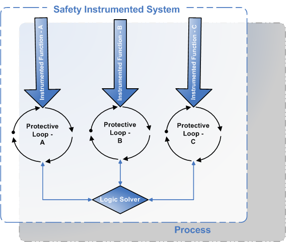
About the Components in a Safety Instrumented System (SIS)
A safety instrumented system (SIS) comprises of instruments that are designed specifically to:
- Monitor the conditions of a process
- Recognize conditions that are indicative of failure
- Prevent consequences
A given process can have more than one SIS in place to monitor and safeguard its conditions.
- Each SIS contains one or more protective instrument loops per instrumented function. The protective instrument loop is a series of interconnected instruments. Each loop is designed to maintain a defined condition within the process, meaning that it serves a specific purpose or a function. In other words, for every instrumented function that exists for a safety instrumented system, there is one protective instrument loop in place to fulfill that function.
- Each SIS contains one logic solver to interpret the readings from the components of the protective instrument loop and instruct those elements to take action if necessary. The logic solver measures that information against predefined criteria to determine whether that system needs to make adjustments to mitigate the risk associated with the instrumented functions of each protective instrument loop.
Functions of Individual Components in an SIS
Assume that Unit A provides steam to Unit B, and SIS-A is in place on Unit A and Unit B to maintain the pressure levels during that process to prevent loss of pressure or excess pressure beyond the defined safe and productive levels. Maintaining safe and productive pressure levels are the instrumented functions of the protective instrument loops within SIS-A. The logic solver within SIS-A receives data from the components of the protective instrument loops and decides whether the pressure levels are normal, or if they exceed or are lower than the safe and productive pressure levels. If the current pressure levels indicate the possibility of a process failure, which includes scenarios like loss of productivity or explosion, the logic solver sends signal to the components of the SIS to do something to mitigate the current condition. For example, if the current condition of the process indicates that the pressure is too low, the logic solver will tell an element of the protective instrument loop to increase the pressure so the levels are within the safe and productive levels defined for that process.
Access the SIS Management Overview Page for all Hierarchy Levels
Before You Begin
- You can access the SIS Management Overview page only if you are a member of one of the following Security Groups:
- MI SIS Administrator
- MI SIS Engineer
- MI SIS User
You can perform the various tasks on this page based on the privileges granted to these Security Groups.
This topic describes how to access the SIS Management Overview page, on which you can access all the information and perform various tasks related to a safety instrumented system (SIS) for all hierarchy levels. If you want to access SIS information related to a particular hierarchy level, you can access the SIS Management Overview page for a particular hierarchy level.
Procedure
The SIS Management Overview page appears.
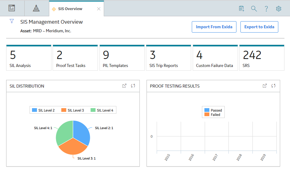
The following information related to all hierarchy levels appears on the page:
- The SIL Analysis tab : Displays a list of SIL Analyses. You can create a new analysis, or access an existing one. The number on the tab indicates the number of SIL Analyses.
- The Proof Test Tasks tab: Displays a list of Proof Test Tasks that are linked to an Instrumented Function or a Logic Solver. The Proof Test Tasks that are created in Asset Strategy Management also appear in the list. The number on the tab indicates the number of Proof Test Tasks.
- The PIL Templates tab : Displays a list of Protective Instrument Loop Templates. You can create a new template, or access or delete an existing one. The number on the tab indicates the number of Protective Instrument Loop Templates.
- The SIS Trip Reports tab: Displays a list of SIS Trip Reports. You can create a new one, or access or delete an existing one. The number on the tab indicates that number of SIS Trip Reports.
- The Custom Failure Data tab: Displays a list of Failure Rate Reference Data records for Sensors, Logic Solvers, and Final Elements. You can create a new one, or access or delete an existing one. The number on the tab indicates the number of Custom Devices.
- The SRS (SRS) tab: Displays a list of SRS Projects. You can create a new SRS Template. The number on the tab indicates that number of SRS Projects.
The page displays the following graphs that correspond to all hierarchy levels:
- SIL Distribution : Plots the number of Protective Instrument Loops with Safety Integrity Levels (SIL) of 1, 2, 3, and 4.
- Proof Testing Results : Plots the number of passed and failed proof tests for the current year and past four years.
By default, the hierarchy level is set to Home and the information that appears on the SIS Management Overview page is related to all Hierarchy Levels, including records that are not associated with any Asset. You can filter the information that appears on the page based on a specific Asset by selecting  in the upper-left corner of the page.
Access the SIS Management Overview Page for a Hierarchy Level
Before You Begin
- You can access the SIS Management Overview page only if you are a member of one of the following Security Groups:
- MI SIS Administrator
- MI SIS Engineer
- MI SIS User
You can perform the various tasks on this page based on the privileges granted to these Security Groups.
This topic describes how to select a hierarchy level (an Equipment or a Functional Location), and then access the SIS Management Overview page for that hierarchy level. You can also access the SIS Management Overview page for all hierarchy levels.
Procedure
- In the top navigation bar, select
 .
.The Asset Hierarchy page appears.

- In the workspace, select the Integrity tab.
The Integrity section appears.
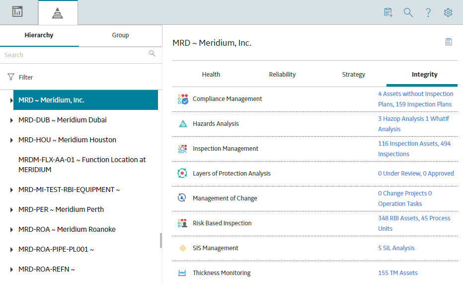
- In the section, in the SIS Management row, select the link.
The SIS Management Overview page for the selected hierarchy level appears.
The following information appears on the page:
- The SIL Analysis tab: Displays a list of SIL Analyses only for the selected asset and all assets within the selected hierarchy. You can create a new SIL Analysis, or access an existing one. The number on the tab indicates the number of SIL Analysis related to the selected Asset.
-
The Proof Test Tasks tab: Displays a list of Proof Test Tasks that are linked to an Instrumented Function or a Logic Solver. The Proof Test Tasks that are created in Asset Strategy Management also appear in the list. The number on the tab indicates the number of Proof Test Tasks.
- The PIL Templates tab: Displays a list of Protective Instrument Loop Templates. You can create a new one, or access or delete an existing one. The number on the tab indicates the number of Proof Test Templates.
- The SIS Trip Reports tab: Displays a list of SIS Trip Reports. You can create a new one, or access or delete an existing one. The number on the tab indicates that number of SIS Trip Reports.
- The Custom Failure Data tab : Displays a list of Failure Rate Reference Data records for Sensors, Logic Solvers, and Final Elements. You can filter based on the type, create a new one, or access or delete an existing one. The number on the tab indicates the number of Custom Devices.
- The SRS (SRS) tab: Displays a list of SRS Projects. You can create a new SRS Template. The number on the tab indicates that number of SRS Projects.
The workspace displays the following graphs that correspond only to the selected hierarchy level:
- SIL Distribution : Plots the number of Protective Instrument Loops with Safety Integrity Levels (SIL) of 1, 2, 3, and 4. These are the Protective Instrument Loops that are related to the selected hierarchy level.
- Proof Testing Results : Plots the number of passed and failed proof tests for the past four years. These are the Proof Tests that are related to the selected hierarchy level.
By default, the hierarchy level is set to Home and the information that appears on the SIS Management Overview page is related to all Hierarchy Levels, including records that are not associated with any Asset. You can filter the information that appears on the page based on a specific Asset by selecting
in the upper-left corner of the page.
SIS Management Workflow
This workflow provides the basic, high-level steps for using this module. The steps and links in this workflow do not necessarily reference every possible procedure.
Conducting an SIL analysis includes completing the following steps:
- Create an SIL Analysis, to store the details of the SIL analysis that you want to perform, including the start and end dates for the analysis.
- Define the SIL analysis team , who will conduct the analysis.
- Define the logic solvers that will monitor the process associated with the instrumented functions and protective instrument loops within the SIL analysis.
- Define the instrumented functions that will be used to maintain safety integrity level within tolerable limits.
- Perform SIL Assessment to determine the target SIL value for each instrumented function in the analysis.
- Perform SIL Verification by creating a Protective Instrument Loop and defining its elements. GE Digital APM then performs the SIL calculations for the loop, and allows you to verify if the target SIL is achieved.
- Perform SIl Validation to ensure that the system is functioning to the standards for which it is designed.
- Link the SIL Analysis to reference documents , which contain reference material relevant to the analysis.
- Propose a Recommendation. Recommendations can be used strategically to propose an action that will mitigate a risk that has been assessed, or tactically to alert another user or create a work request to resolve an issue.