 Web HMI
Get Started with iFIX and Web HMI
When using the iFIX HMI/SCADA system as your data source, follow this workflow to successfully get data and alarms transferring in to Web HMI for the first time.
- First install iFIX, and then install Web HMI on the same server.
- Check the Task Configuration list of the iFIX System Configuration Utility (SCU) to verify these programs are installed on the Web HMI server:
- AlarmGateway.exe: Subscribes to OPC alarm and event messages from the iFIX OPC AE server and posts them to the RabbitMQ service for the Alarm microservice to manage.
- DataDistributor.exe: Routes data requests to the proper source and efficiently returns the requested data.
Note: Scadastat.exe is deprecated. You may still see it running during a Web HMI upgrade as an iFIX task. This does not impact iFIX and you can safely remove it from the iFIX SCU. - Verify that iFIX SCU Network Configuration on the Web HMI server has networking enabled and the remote SCADA nodes (if any) display in its remote node list.
- Launch the Web HMI shortcut on the desktop to load the default Web HMI URL in your browser and load Web HMI Runtime. If security warnings appear, verify that your browser meets the minimum requirements and the appropriate CA certificates are installed.
- In iFIX, do the following:
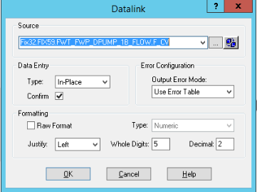
- To enable a Web HMI operator to update an iFIX data source tag on a picture and answer an update confirmation question, access the Datalink screen and select the source tag. In the Data Entry section, select In-Place in the Type field, and then select the Confirm check box, as shown below.
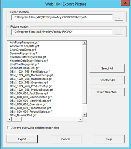
- In the iFIX Tools Ribbon, select Web HMI Export Picture to export selected pictures in GRF format in to a Picture folder as shown below. These GRF files are exported in to JSON ZIP files. These pictures become mimics (process diagrams) that you associate with asset object types in Web HMI.
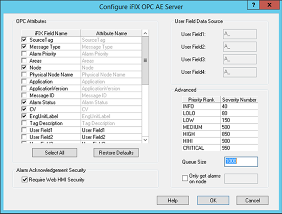
- Verify the values in the Advanced section of the Configure iFIX OPC AE Server screen conform to the OPC A&E specification guidelines and use the Web HMI default dividing point values to separate the alarm severity ranges, as explained in Alarm Microservice.The following provides a sample Configure iFIX OPC AE Server screen.
- To enable a Web HMI operator to update an iFIX data source tag on a picture and answer an update confirmation question, access the Datalink screen and select the source tag. In the Data Entry section, select In-Place in the Type field, and then select the Confirm check box, as shown below.
- In the Web HMI Administration environment, perform the following tasks:
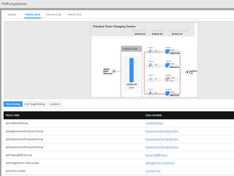
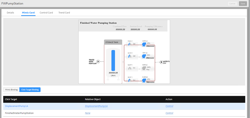
- Bind the imported mimics to asset object types in the model using the object type list. The following shows the mimic fields bound to the data variables of the Finished Water Pumping Station object type:
- Set up the navigation of mimic click targets. You define the click target to navigate to any asset in the model or to open a Control View where an operator can modify HMI/SCADA real-time values (if permitted in the HMI/SCADA source) and view historical data. In the following example, the FWPumpStation is set with a Control Action to open a Control View when an operator selects the DisplacementPump1A object in the mimic.
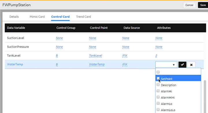
- Define the content for Control Views on the Control Cards. You can group related asset data variables together to appear in a Control View by specifying a group identifier in the Control Group column. In this example, the TankLevel and WaterTemp variables are grouped together, and both have Control Points that enable an operator to modify their current values in iFIX. Both TankLevel and WaterTemp are acting as their own Control Points, which means an operator is writing to and reading from the same variable tag. In some instances, a Control Point can be a separate variable tag. For example, TargetTemperature is the Control Point for ActualTemperature. If you modify the temperature of TargetTemperature, ActualTemperature gradually changes to that temperature.
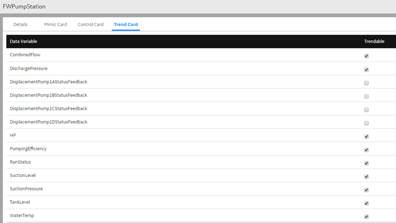
- Select the data variables of an asset object type to appear as trend lines in a Trend Card, as shown below:
Note: For detailed information about the above tasks, see Develop Runtime Content. - Bind the imported mimics to asset object types in the model using the object type list. The following shows the mimic fields bound to the data variables of the Finished Water Pumping Station object type:
- Switch to Runtime to view data and alarms appearing in the correct context and cards.If iFIX is unable to write or acknowledge alarms, check the
secmgr.cclr.dll.configfile in the iFIX install folder on the SCADA node to verify it contains the correct host or port for the Web HMI server.