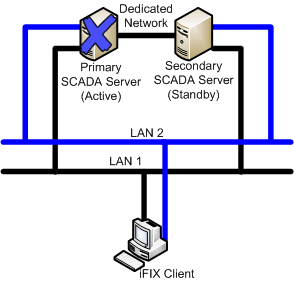
This example shows a Redundant Local Area Network (2 LANs) for Redundant iFIX networking and one dedicated LAN between the SCADA failover pair as the primary network for database synchronization. Also in use are the iFIX networking networks as the Secondary and Tertiary networks for database synchronization
The following scenarios, illustrated in more detail below, describe failure situations that can occur:
- Primary SCADA Unavailable
- Secondary SCADA Unavailable
- Both Primary and Secondary SCADA Unavailable
- Primary SCADA Server Connection to LAN1 or LAN2 Failed
- Secondary SCADA Server Connection to LAN1 or LAN2 Failed
- Network to Primary SCADA from the Client Unavailable
- Network to Secondary SCADA from the Client Unavailable
- Dedicated Network Between Primary and Secondary Unavailable
- Complete Network Failure
- Both LAN1 and LAN2 Fails
- Network LAN 1 or LAN 2 Fails
The sections that follow describe the recovery state of the primary SCADA, secondary SCADA, and iClient should one of these scenarios occur.
Scenario 1: Primary SCADA Unavailable
The following example illustrates two local area networks (LANs), with a dedicated network for SCADA synchronization, and a single failure point.
The following table describes the items in the previous figure.
|
Item |
State |
|
Primary SCADA Server |
Unavailable. |
|
Secondary SCADA Server |
Switches to Active. No Synchronization. |
|
iFIX Client |
The iFIX Client detects loss of communication to the primary node and switches to the newly active node. The iFIX Client generates a system message that communication was lost to the primary SCADA node. The Client obtains data and alarms from the secondary SCADA. |
Scenario 2: Secondary SCADA Unavailable
The following example illustrates two local area networks (LANs), with a dedicated network for SCADA synchronization, and a single failure point.

The following table describes the items in the previous figure.
|
Item |
State |
|
Primary SCADA Server |
Active. No Synchronization. |
|
Secondary SCADA Server |
Unavailable. |
|
iFIX Client |
The iFIX Client detects loss of communication to secondary node. The iFIX Client generates a system message that communication was lost to secondary SCADA node. The Client obtains data and alarms from the primary SCADA. |
Scenario 3: Both Primary and Secondary SCADA Unavailable
The following example illustrates two local area networks (LANs), with a dedicated network for SCADA synchronization, and two failure points.

The following table describes the items in the previous figure.
|
Item |
State |
|
Primary SCADA Server |
Unavailable. |
|
Secondary SCADA Server |
Unavailable. |
|
iFIX Client |
The iFIX Client generates a system message that communication was lost to both the primary and secondary SCADA nodes. The iFIX Client fails to obtain data and alarms. |
Scenario 4: Primary SCADA Server Connection to LAN1 or LAN2 Failed
The following example illustrates two local area networks (LANs), with a dedicated network for SCADA synchronization, and a single failure point, in two different scenarios.

The following table describes the items in the previous figure.
|
Item |
State |
|
Primary SCADA Server |
Active. Synchronization occurs over dedicated network. |
|
Secondary SCADA Server |
Standby. Since the active and standby nodes are communicating over the dedicated network, they never switch. |
|
iFIX Client |
The iFIX Client generates a system message that the connection switched to LAN1 or LAN2. The Client continues to obtain data and alarms from the primary SCADA. |
Scenario 5: Secondary SCADA Server Connection to LAN1 or LAN2 Failed
The following example illustrates two local area networks (LANs), with a dedicated network for SCADA synchronization, and a single failure point, in two different scenarios.
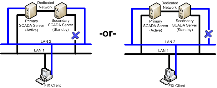
The following table describes the items in the previous figure.
|
Item |
State |
|
Primary SCADA Server |
Active. Synchronization occurs over dedicated network. |
|
Secondary SCADA Server |
Standby. Since the active and standby nodes are communicating over the dedicated network, they never switch. |
|
iFIX Client |
The iFIX Client generates a system message that the connection switched to LAN1 or LAN2. The Client continues to obtain data and alarms from the primary SCADA. |
Scenario 6: Network to Primary SCADA from the Client Unavailable
The following example illustrates two local area networks (LANs), with a dedicated network for SCADA synchronization, and two failure points.

The following table describes the items in the previous figure.
|
Item |
State |
|
Primary SCADA Server |
Active. Synchronization occurs over dedicated network. |
|
Secondary SCADA Server |
Standby. Since the active and standby nodes are communicating over the dedicated network, they never switch. |
|
iFIX Client |
The iFIX Client switches to the standby SCADA and fails to obtain up-to-date data directly from the active SCADA. The iClient reads data through the standby SCADA but will not get new alarms. The iFIX Notification message displays in this situation. Writes from the iClient node are not allowed. |
Scenario 7: Network to Secondary SCADA from the Client Unavailable
The following example illustrates two local area networks (LANs), with a dedicated network for SCADA synchronization, and two failure points.

The following table describes the items in the previous figure.
|
Item |
State |
|
Primary SCADA Server |
Active. Synchronization occurs over dedicated network, if configured. |
|
Secondary SCADA Server |
Standby. |
|
iFIX Client |
The iFIX Client generates a system message that communication was lost to the secondary SCADA node. The Client continues to obtain data and alarms from the primary SCADA. |
Scenario 8: Dedicated Network Between Primary and Secondary Unavailable
The following example illustrates two local area networks (LANs), with a dedicated network for SCADA synchronization, and a single failure point.

The following table describes the items in the previous figure.
|
Item |
State |
|
Primary SCADA Server |
Active. Synchronization occurs over LAN1 or LAN2. |
|
Secondary SCADA Server |
Standby. |
|
iFIX Client |
The Client continues to obtain data and alarms from the primary SCADA. |
Scenario 9: Complete Network Failure
The following example illustrates two local area networks (LANs), with a dedicated network for SCADA synchronization, and multiple failure points. In this example, the dedicated network between the primary and secondary SCADA is unavailable. The network from the primary SCADA to the Client is unavailable. The network from the secondary SCADA to the Client is also unavailable.

The following table describes the items in the previous figure.
|
Item |
State |
|
Primary SCADA Server |
Active. No Synchronization. |
|
Secondary SCADA Server |
Switches to Active. No Synchronization. |
|
iFIX Client |
The iFIX Client generates a system message that communication was lost to both the primary and secondary SCADA nodes. The iFIX Client fails to obtain data and alarms. |
Scenario 10: Both LAN1 and LAN2 Fails
The following example illustrates two local area networks (LANs), with a dedicated network for SCADA synchronization, and multiple failure points. The LAN1 and LAN2 networks from the primary SCADA to the Client are unavailable. The LAN1 and LAN2 networks from the secondary SCADA to the Client are also unavailable.

The following table describes the items in the previous figure.
|
Item |
State |
|
Primary SCADA Server |
Active. Synchronization occurs over dedicated network. |
|
Secondary SCADA Server |
Standby. |
|
iFIX Client |
The iFIX Client generates a system message that communication was lost to both the primary and secondary SCADA nodes. The iFIX Client fails to obtain data and alarms. |
Scenario 11: Network LAN 1 or LAN 2 Fails
The following example illustrates two local area networks (LANs), with a dedicated network for SCADA synchronization, and multiple failure points, in two different scenarios.

The following table describes the items in the previous figure.
|
Item |
State |
|
Primary SCADA Server |
Active. Synchronization occurs over dedicated network. |
|
Secondary SCADA Server |
Standby. Since active and standby nodes are communicating over the dedicated network, they never switch. |
|
iFIX Client |
The iFIX Client generates a system message that the connection switched to LAN1 or LAN2. The Client obtains data and alarms from the primary SCADA. |
Important Notice
You do not have the latest version of iFIX! You are missing out on the newest capabilities and enhanced security.
For information on all the latest features, see the iFIX product page.
For more information on upgrades, contact your GE Digital sales agent or e-mail [email protected].
For the most up-to-date documentation, go here.
